
I’ll admit it. I have a borderline unhealthy amount of respect for old school vacuum fluorescent displays.
Yah, they are clunky and fragile. They burn in. They demand 40 volts to run. Still, they earn their keep with that unmistakable, retrofuturistic neon-green glow. They are now arguably obsolete, and it makes them rare and expensive.
I snagged this VFD clock from Aliexpress for $20:


There were no part numbers nor documentation on the listing. But there aren’t a lot of companies still making these displays. I expected to quickly find a similar part from one of them.
I looked at many 16x2 VFD displays online. None seemed to match the pinout. CU16025ECPB looked promising, but not an exact match. The BC-VFD line of Noritake displays with built-in, HD44780-compatible controllers also looked similar, but they don’t offer a 16x2 model, nor do they match the serial data I see from the display.
It was only after I reversed the protocol, as I’m finishing writing this article, that I finally found some documentation for this exact display. Scroll to the bottom for it, but I think the blind journey is still worth it.
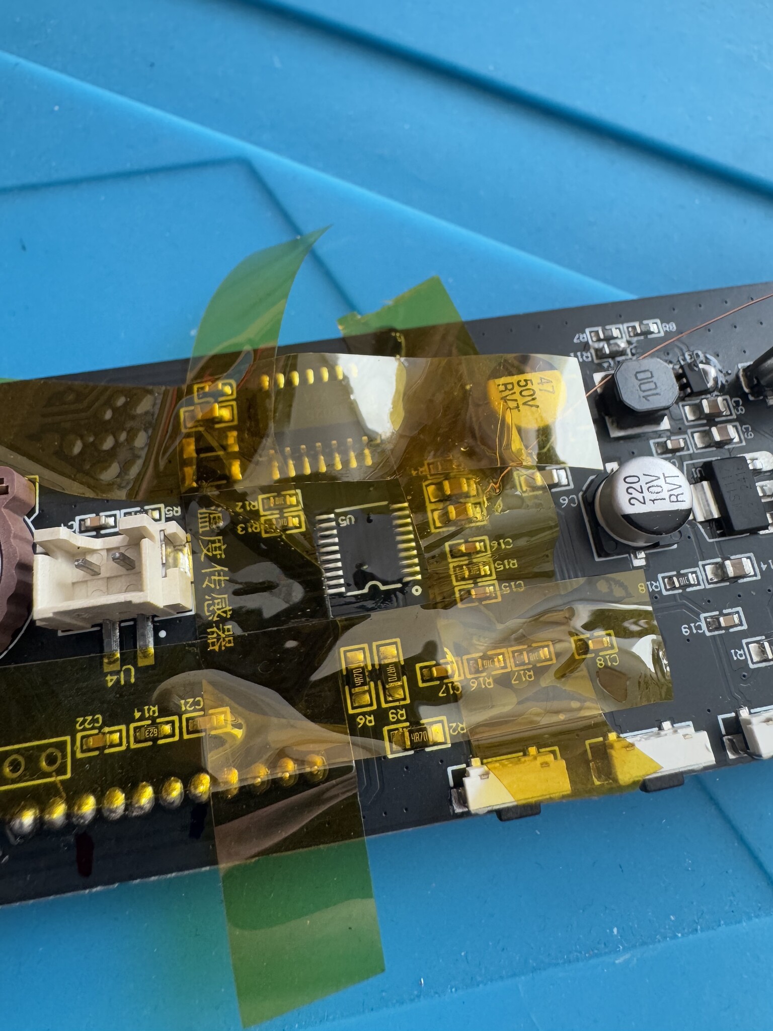
These are the components I identified on the board:
| Description | Component |
|---|---|
| Main microcontroller | Cortex-M0+ HC32F005 |
| Real-time clock | RX8025 |
| 5V -> 3.3V LDO | AMS1117 |
| 5V -> 37V boost converter | Likely the tiny SOT-23 package on the bottom left partially marked 302, close to the 100 inductor and Schottky diode |
I’ve never seen this MCU before. I found the pinout from the (chinese-only) datasheet:

I knew vacuum fluorescent displays required high voltage to operate. The first step was to identify the high voltage pins so I don’t fry my equipment.
Next, I looked for display pins connected directly to the MCU. I found four by testing for continuity. I hooked the logic analyzer and this is what I saw for three of them:

It sure looks like data and clock. I put together this partial pinout map:

| Pin no. | Function |
|---|---|
| 1,2 | Filament + |
| 3, 4 | Ground |
| 5 | High voltage supply, 37 V |
| 6 | Low voltage supply, 3.3 V |
| 8 | Display enable (active low) |
| 9 | Chip select (active low) |
| 10 | Clock |
| 11 | Data |
| 14, 15 | Filament - |
After boot, the clock animates > and < characters and writes "HELLO!!!" on the screen:

This is what the signals look like when it happens:

I noted that that the clock idles at HIGH. With this, we can already decode the data into bytes.
To send a byte over the wire, we have the choice of sending either the least of the or most significant bits (LSB/MSB) first. Both would work, but there’s a hidden hint here. Selecting LSB, we can match the decoded "HELLO!!!" bytes to their ASCII values:

In the same sequence, the preceding byte from the character maps to a column. The one before that refers to the row. A sequence like 0x10 0x0B 0x48 means:
0x01: second row0x0B: 11th column (counted right to left)0x48:Hcharacter
The initialization sequence contains 0x70 0x6c. I also recorded the data while changing the brightness. Bytes 0x53 VAL controls the brightness from 0x00 to 0xff.
We can now push some text to the display. I hooked an ESP32 to the data lines and wrote this ESPHome driver. I used it to generate the first photo on this article:
esphome:
  name: vfd-display
  friendly_name: VFD Display
  on_boot:
    priority: -100
    then:
      - lambda: |-
          id(my_vfd).clear();
          id(my_vfd).print(0, 0, "Hello, world");
          id(my_vfd).print(0, 1, "      rbaron.net");

external_components:
  - source:
      type: git
      url: https://github.com/rbaron/esphome
      ref: vfd16x2
    components: [vfd16x2]
I initially desoldered the built-in MCU from the board. I then realized I could’ve just permanently shorted its reset pin to ground and let the ESP32 do all the talking. I ended up putting it back on:

Luckily the display fit in one of the spare enclosures from my sheet metal fabrication experiment:


The character set is neither standard ASCII nor ISO 8859-1. Here are all built-in special characters:


Mystery Solved
By accident, while I was writing this article, I found the same standalone display under the name CIG25-1605N on Aliexpress. The description mentions part number SVC1602A. This listing has schematics and a link to the datasheet! There I also confirmed that the 302 marked part is a boost converter (LGS6302).
We can now interpret the init commands we saw above:
| Command | Description |
|---|---|
0x70 |
Display light set: normal operation. As opposed to all lights off or on |
0x6C |
Set number of digits: 16 |
The datasheet explains how to create custom characters. With 16 slots per row, we can draw any pattern on the display. This lil’ wave is done by assembling custom chars every 100 ms:
Single-row wave
Double-row wave